At the heart of every hydraulic system, the directional valve (or directional valve) performs an essential task: directing the oil flow towards the actuators, controlling movements and functions of the entire system. If you are looking for on/off directional valves or proportional directional valves, it is essential to first know how to connect them correctly.
A correct connection of hydraulic directional valves is essential to ensure efficiency, safety and system longevity. Even a seemingly trivial error (a reversed tube, an undersized fitting, an obstructed return line) can generate overheating, cavitation, pressure drops and malfunctions capable of compromising productivity or damaging expensive components.
This guide is designed for designers, technicians and maintenance personnel who want to understand how to correctly connect directional valves, recognize the most frequent errors and apply best design and maintenance practices.
Why correct connection of directional valves is essential
The directional valves represent the logical core of the hydraulic circuit. Through their actuation (manual, electrical or pilot-operated), they define the fluid path between pump, reservoir and actuators (cylinders or hydraulic motors).
An incorrect connection can cause a chain of consequences: oil overheating, pump cavitation, pressure drops along the lines, abnormal actuator movements and premature wear of seals and mechanical components.
In a well-designed circuit, every connection must ensure that the flow follows a defined and balanced path, both in working and resting conditions, without generating undesired pressures or internal recirculation zones. To fully understand the role of the directional valve in the system, it is also useful to recall the operation of the hydraulic pump, covered in detail in the article How a hydraulic pump works: main types and applications.
Symbology and operating logic according to ISO 1219-1
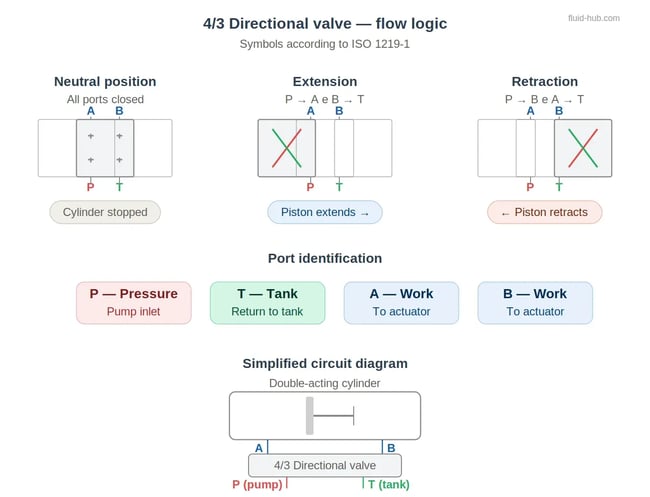
To correctly read and create connection diagrams, it is essential to know the standardized symbology defined by the standard ISO 1219-1. Each directional valve is graphically represented by a number of ways (connection ports) and positions (switching states). For example, a 4/3 valve indicates four ways (P, T, A, B) and three positions (advance, neutral and return).
The main ports identified in the diagrams are:
-
P (Pressure): pump inlet and circuit supply.
-
T (Tank): return to reservoir.
-
A and B: work lines to the actuators (cylinders or motors).
-
In some cases: X and Y as external pilot lines, used in proportional or remote-controlled valves.
Descriptive example: 4/3 valve with closed center
Let us imagine a 4/3 valve with closed center mounted on a circuit with a double-acting cylinder. In the neutral position all ways are blocked: the pump remains under pressure and the cylinder is stationary. Moving the spool to the right opens the P-A and B-T connection: the oil pushes the piston forward while the fluid expelled from the opposite side returns to the reservoir. Reversing the command, the flow goes from P to B and from A to T, retracting the piston.
This symbology, codified by the standard ISO 1219, allows immediate visualization of the flow logic and to immediately identify any connection or calibration errors.
Most common types of connection diagrams
Depending on the type of pump, circuit configuration and application, directional valves can be connected according to different center configurations. Let us see the main ones.
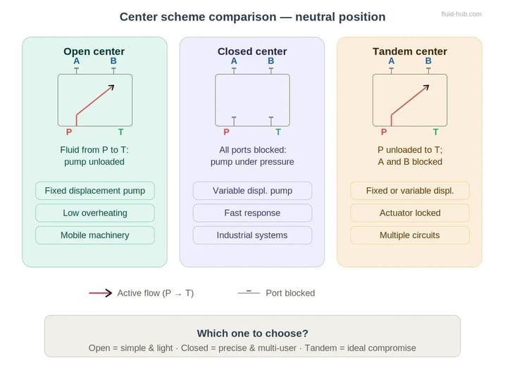
Open center configuration
It is the simplest and most widespread configuration in circuits with fixed displacement pump, such as gear pumps.
In neutral position, the fluid from the pump flows freely from P to T, discharging into the reservoir. The system does not remain under pressure when the actuator is stationary, reducing energy consumption and oil overheating.
This configuration is ideal for systems with a single user at a time, as in agricultural and mobile machines. It is instead poorly suited for circuits with multiple simultaneous users, since the flow cannot be maintained under pressure on multiple lines.
Closed center configuration
In this configuration, in neutral position all valve ways are closed: the fluid cannot circulate and the pump maintains pressure in the circuit. To avoid overpressure, it is necessary to use a variable displacement pump (for example a variable flow piston pump or a variable flow vane pump) or a compensation system that reduces flow in the absence of demand.
The closed center allows feeding multiple independent users and offers a very responsive command, being ideal for complex industrial systems, machine tools and proportional systems. However, it requires more accurate design and higher precision components, including proportional valves and pressure regulating valves.
Tandem configuration
In the tandem center, the P way is connected to T (as in open center), while ways A and B remain closed. In neutral position, the flow returns to the reservoir at low pressure, keeping the pump unloaded, but the actuator remains locked in its position. It is a widely used intermediate solution in multiple circuits where only one user operates at a time.
Parallel and series connection
In parallel connection, multiple directional valves receive oil from the same pressure line P with common return T. Each user can operate independently, but the total flow is divided among the valves: correct pump sizing and the use of flow compensator valves to keep actuator speed constant are therefore necessary.
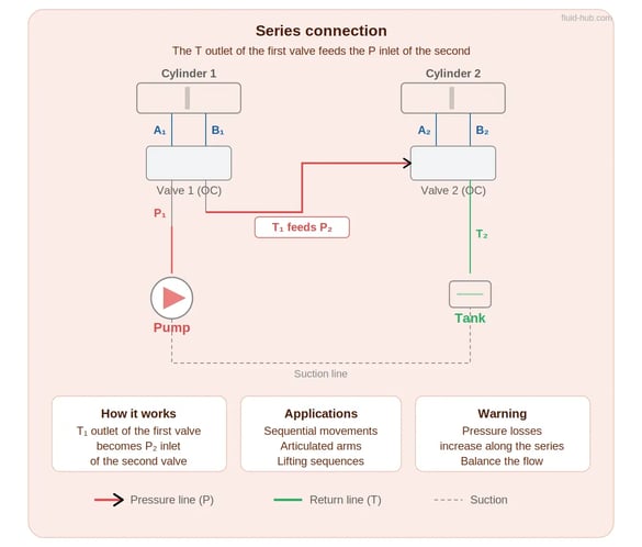
 In series connection, the output of the first directional valve feeds the next one. This configuration is useful when movements must occur in sequential order (for example on articulated arms or lifting sequences), but involves increasing pressure drops along the line and requires careful flow balancing. For more details on the structure of a complete system, see the article How to build a hydraulic power unit: complete guide.
Comparison of the main center configurations
The following table summarizes the main characteristics of the three most commonly used center configurations.
|
Configuration |
Ports in neutral |
Recommended pump |
Applications |
Main advantages |
|
Open center |
P connected to T; A e B closed |
Fixed displacement |
Agricultural and mobile machines |
Low overheating, simplicity |
|
Closed center |
All ways closed |
Variable displacement or with compensator |
Industrial plants, machine tools |
Quick response, independent users |
|
Tandem |
P connected to T; A e B closed |
Fixed or variable displacement |
Multiple circuits, one user at a time |
Pump unloaded, actuator stationary |
The choice of configuration also depends on the type of pump adopted: to guide your selection, see our guide to choosing a hydraulic pump.
Common mistakes in connecting hydraulic directional valves
Connection errors are among the most frequent causes of malfunction and reduced system efficiency. Here are the most common:
-
Reversal of lines A and B: causes opposite actuator movement, with risk of mechanical damage and danger to operators.
-
Incorrect connection between P and T: causes immediate overheating and risk of pump failure due to overpressure.
-
Undersized return to reservoir: generates backpressure in the T line, promoting cavitation and noise. A return filter correctly sized is essential.
-
Absence of safety valves: exposes the circuit to uncontrolled overpressures. Pressure regulating valves must always be present.
-
Piping too long, narrow or curved: increase pressure drops and can cause vibrations and water hammer. Choose quality fittings of adequate quality
-
Unsuitable seals or fittings: seals unsuited to operating pressure or temperature generate micro-leaks and contamination.
-
Fluid contamination: assembly in dirty environments or without adequate filtration introduces particles that damage valve spools and seats.
⚠ WARNING: An obstructed or poorly sized T return is one of the main causes of overheating and noise in hydraulic power units. A preventive check of the discharge line avoids costly failures and extends the life of the pump and hydraulic motor. To learn more about the operation of motors, consult the dedicated article on the fluid-hub blog.
Practical tips for a correct connection
During design
Verify the compatibility between the pump type and the chosen valve configuration (open, closed or tandem center). Ensure that fittings and piping have a diameter adequate for the flow rate and operating pressure, and that the circuit is equipped with check or compensator valves to ensure system stability.
Always provide an efficient filtration system, positioning pressure filters or return filters at strategic points. The use of dedicated CAD software or symbol libraries compliant with the standard ISO 1219 allows verifying the correct flow path already in the design phase, drastically reducing errors on site. The adoption of digital tools such as Digital Twins can further improve design quality.
💡 PRACTICAL TIP: Drawing the diagram with ISO symbols and consistent numbering between pump, valves and actuators facilitates both testing and future maintenance. Each line should be identified with P, T, A, B labels directly on the diagram and on the physical piping.
During assembly
Thoroughly clean pipes, fittings and valves before installation, avoiding the entry of contaminating particles. Respect the tightening torques specified by the standards (for example ISO 8434 for threaded or bite-type fittings). Clearly identify lines P, T, A and B to prevent reversals: a simple error at this stage can cause complete circuit malfunction.
Check the mounting direction of the valve, the correct position of seals and ensure that piping does not have tight bends or crushing. Verify that the fluid cleanliness level is compliant with the valve manufacturer’s specifications, referring to the standard ISO 4406 for contamination classification.
During maintenance
Carry out periodic pressure and flow checks with pressure switches and pressure transducers certified, verifying the absence of micro-leaks on fittings. Keep the oil level and cleanliness within recommended limits and monitor fluid temperature: an abnormal increase may indicate internal recirculation, backpressure on the T line or wear of the valve sealing elements.
A preventive maintenance on directional valves and return filters extends the useful life of the system and reduces unplanned machine downtime. Document each intervention with date, recorded values and replaced components: this traceability is the first step towards effective predictive maintenance.
💡 PRACTICAL TIP: After each maintenance intervention, perform a low-pressure test with filtered oil to ensure the absence of reversals, internal obstructions or abnormal leakage. Only after this verification gradually bring the circuit to operating pressure.
Useful tools for design and control
To best manage the connection of hydraulic directional valves, it is advisable to have some essential tools:
-
CAD software with ISO 1219 libraries: allow drawing diagrams compliant with standards and visually verifying the flow logic before physical implementation.
-
Valve selection tables: provided by leading manufacturers such as Bosch Rexroth and Parker, help choose the center type and correct size based on flow rate and operating pressure.
-
Certified measuring instruments: pressure switches, pressure transducers, flowmeters and thermometers for periodic checks.
-
Assembly checklist: an operational document listing checks to be performed before, during and after installation drastically reduces errors.
-
Online configurators: modern online configurators and quotation tools simplify component selection and speed up procurement.
For rapid procurement of necessary components, specialized industrial e-commerce platforms (link art.32) such as fluid-hub allow finding valves, filters and fittings with real-time availability.
Conclusion
The correct connection of hydraulic directional valves is an essential condition for the safety, efficiency and reliability of the entire system. Knowing the different center configurations, respecting the symbology ISO 1219 and applying good assembly and maintenance practices reduces failures, consumption and machine downtime.
On the blog of fluid-hub you can find further insights dedicated to the design and maintenance of hydraulic circuits, including guides on how a hydraulic pump works, how to choose the right hydraulic motor and how to build a hydraulic power unit. If you have doubts about which valve to choose or how to configure your circuit, explore our hydraulic valves catalog or contact the technical team.